Define noise, control, signal (input), and response (output) factors for your system

PARAMETER DIAGRAM
OVERVIEW
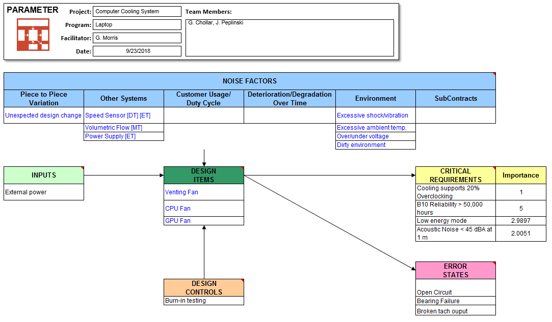
The Parameter Diagram takes the inputs from a system/customer and relates those inputs to desired outputs of a design that the engineer is creating while also considering non-controllable outside influences. Parameter Diagrams are usually created before a FMEA session and after a Boundary Diagram is created.
FEATURES
- Automatically create a Parameter Diagram by importing information from a Requirements worksheets and Boundary Diagram worksheet.
- Interactively add and delete rows in each section
- Define relationships between: (1) Design Items and Critical Requirements and (2) Noise Factors and Critical Requirements.
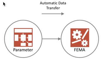
- Use linked relationships to automatically created a FMEA worksheet.
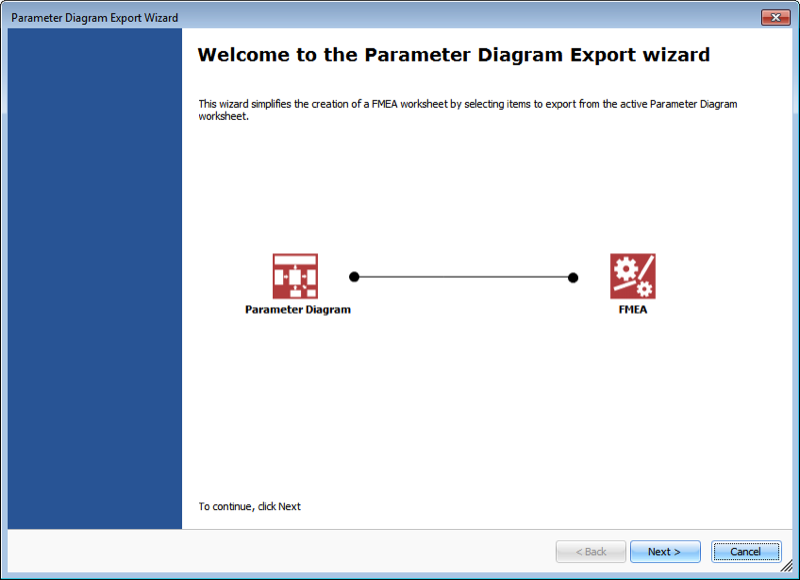
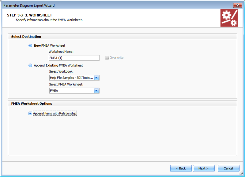
- Export wizard to guide the creating of a FMEA worksheet.
BENEFITS
As a useful tool in brainstorming scenarios for your process or product, the Parameter diagram charts several factors:
- A list of Design Parameters or control factors.
- A set of Outputs, usually a set of characteristics related to product performance or functions, or customer desired characteristics.
- A list of Noise Factors (environmental variations, user conditions, manufacturing variations that cannot be sufficiently controlled.
- A list of of Input items that provide an input interface to the design choice (topic item).
REQUIREMENTS
- Microsoft Windows 7, 8, 10, 11
- Microsoft Excel 2016, 2019, 2021, 365
- WARNING: SDI Tools does not support these versions of Office 365 (Office from Microsoft Store, Office Online, Office for Mac, Office for iOS)
- Administrator rights required to install software
EXPORTING
- Use linked relationships to automatically created a FMEA worksheet.
- Export wizard to guide the creating of a FMEA worksheet.


